This is just about some enhancements I made to my previous projects (1) and (2). They were implemented on my other platinum IIe. I improved on the system cooling by over 45% and also on the AC power wiring
arrangement to better accommodate systems with different peripheral cards. Lastly,
I did it with the illuminated switch!
Better Cooling
Regarding the auxiliary cooling fans used in my previous projects, there
are many makes and models with different dimensions, rotational speeds and noise
levels. I believe two smaller "40DD" (i.e. 40x40xDDmm) fans give the best look. If opening 12 (the one above the PSU cutout) is occupied, a "6025"
fan is the biggest that will fit (barely) in that space behind the RQ-85B PSU. Otherwise you could use a "7020" fan for maximum cooling (A "7025" will not fit because the back of the IIe is not exactly vertical).
The two 40x40x15mm fans in my last project (2) have a total axial flow of 13.0 CFM (cubic foot per minute, equivalent to 0.368 m³/min) compared to 23.5 CFM (0.666 m³/min) of the
single 60x60x25mm fan in my original project (1). I finally opted for the look and switched to two 40x40x25mm fans with a total axial flow of 19.1 CFM
(0.541 m³/min). Nevertheless, bigger fans give better air flow on top of the PSU and also tend to have a lower pitch noise which
is more pleasant to the ears.
I used
two high strength neodymium magnets (from
hardware store) taped to the fan assembly to adhere it to the IIe’s steel
bottom pan. This gives the fan assembly freedom of movement in case you need that
space for temporary work or as a relief when the fan assembly is accidentally
hit by external object. Those IIes with aluminum (non-magnetic) bottom pan are out of luck
here (as in my original project (1) ;-).
Illuminated Switch
I make
sure I get the right switch with the neon discharge lamp inside this time. The easiest way to check if the switch was illuminated is to connect it to the household AC power source and turn the switch on (please be extra careful here!).
I used the two terminals behind the “off” position for switching and the two
behind the “on” position for illumination.
Better Wirings
I chose to have the AC power wires go over the peripheral cards instead of to have everything hide at the back behind the peripheral cards. The ferrite bead was placed down the AC power wires and above the PSU to avoid physical interference with the peripheral cards. To prevent EMI crosstalk due to their proximity to the peripheral cards, the AC power wires were shielded with copper foil and sleeved with heat shrinks wherever necessary.
I chose to have the AC power wires go over the peripheral cards instead of to have everything hide at the back behind the peripheral cards. The ferrite bead was placed down the AC power wires and above the PSU to avoid physical interference with the peripheral cards. To prevent EMI crosstalk due to their proximity to the peripheral cards, the AC power wires were shielded with copper foil and sleeved with heat shrinks wherever necessary.
Some extra
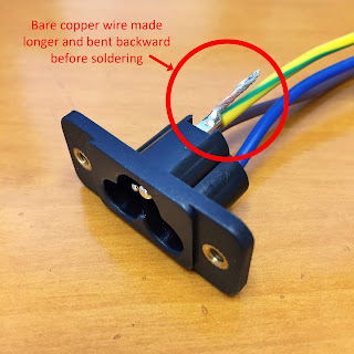
length of bare copper wire was left at the Earth terminal of the C6-inlet to ground
the copper shield. The solder joint was heat shrunk as usual.
My other platinum IIe had connector
openings 8 and 9 free so the C6-inlet was installed in opening 9. Crimp-spade connectors were used on
both the N (Neutral) and L (Live) power wires for connecting to the
illuminated switch. Copper foil was wrapped around the power wires from the
C6-inlet to just before the connectors.
The bare
copper wire from the E (Earth) terminal
on the C6-inlet was soldered to the copper foil and the power wires from the
C6-inlet to the crimp-spade connectors were sleeved.
The
crimp-spade connectors were connected to the switch and copper foil continually wrapped around
the AC power wires until there is sufficient length to cross over the
peripheral cards in the lower-numbered slots. The copper foil was then metered to make sure it was earthed
properly. This section of the AC power wires was sleeved afterward.
I reinstalled all the peripheral cards and everything got slightly but surely more space than in my last project (2). Using openings 8 and 9 (between slot 1 and 2) also improved the layout of the AC power wirings and cablings as there was less physical interference with the peripheral cards.
My other platinum IIe finally got her “new lease of power”. I
hoped everything was done right this time!
Thank
you again for visiting!
Dream your Apple II dream!


